Over on his blog, Yashin has written a post showing how to analyze 433 MHz transmitters using several methods. Devices that transmit using low power 433 MHz are common and often include devices such as weather monitors, power monitors and alarm sensors.
To show his analysis methods Yashin used an ASK modulated FS1000A 433 MHz transmitter connected to an Arduino Teensy microcontroller. He first uses GQRX and baudline together with an RTL-SDR in Kali Linux to test that the transmitter is working and to visually inspect the RF spectrum. Then he shows how to use GNU Radio to receive the 433 MHz transmitter and how to record an audio file. The final tool he shows how to use is rtl_433 which will automatically decode the data into binary strings using the analysis option.
Xastir is a Linux based program that is used for plotting Automatic Packet Reporting System (APRS) data on a map. APRS is is type of packet radio system used by ham radio for real time local area digital communications. It is often used for sending messages, plotting positions on a map or providing weather station data.
At Tel-Aviv University in Israel, two students undertook a class project where they were able to use an RTL-SDR to record a garage door opener signal and then use a Texas Instruments (TI) Chronos watch to retransmit a copy of the signal. Their report can be found here (pdf). The TI Chronos is a wrist watch with a built in programmable ISM band RF transmitter.
The students report contains an analysis of the signal which may be of use to anyone interested in decoding their own ISM band signals and they also describe a method used to automatically obtain the required parameters for programming the TI Chronos with the signal to be copied. The abstract of their report is as follows
We present a simple and affordable way of copying remote controls widely used for parking lot gates, garage doors and other simple systems. These simple remote controls usually use a fixed code (as opposed to the more secured rolling code used for car keys remote controls) and a simple On-Off Keying (OOK) modulation, over 433.92MHz in the ISM band. We suggest the use of the TI-Chronos wrist-watch platform for the emulation of the remote control, as this platform transmits in the same band, and can be programmed to emulate different modulations and to send user pre-defined signals.
In this report we show the complete process for copying a remote control into the Chronos platform. This process utilizes only a standard PC and low-cost hardware (less than $75 all together), alongside free software, and additional software developed by us. The process starts with recording the original remote control RF signal. It continues with automatic analysis of the recording, extracting the needed parameters of the signal. Finishing the process, we set the Chronos with those parameters. We demonstrate the copy process using a 4-channel remote control and its receiver board.
The popular YouTube electronics channel Hak5 has uploaded a video showing how they analyzed GSM signals using an RTL-SDR, Wireshark and Airprobe. In their video they use parts of our analyzing GSM tutorial and explain and show visually how to set up all the software.
Using these methods they were able to receive GSM data from a base tower and see various system information.
Over on YouTube user John Miller has uploaded a video showing an example of DSD+ decoding an NXDN96 voice signal. NXDN is a digital voice protocol by developed by Kenwood that is often used by public safety organizations.
John uses SDR# to receive the NXDN signal and then pipes the audio to DSD+ using Virtual Audio Cable for decoding.
There is a war going on between game console designers and the console modding community. Modders hack the console system so that they can jailbreak it and then install their own custom firmware while console designers are constantly finding new ways to prevent unauthorized modding. Custom firmware allows a console to run homebrew applications like media players and emulators that use the console in ways that is was not intended to be used in.
One PlayStation 3 modder has recently been using an RTL-SDR to help jailbreak a PlayStation 3 Super Slim (4K) console, whose current official firmware appears to not yet have been jailbroken. It’s important to note that so far no actual jailbreaking has been done with this method, but the modder is currently working on it. His idea is to receive leaked RF signals from the PS3 and then use methods similar to Acoustic Cryptoanalysis to decode the data and find out what opcode operations the processors are performing. The modder writes about his method in the following.
My idea was to hook up a rtl-sdr device to the PS3 4k between chassis and real ground (yes, I actually have a two meter copper rod buried in my lawn) using the antenna leads. First I had to make sure the PS3 4k chassis wasn’t grounded in the outlet, and that no video out or USB connector was hooked up to ground indirectly via other hardware. If you want to try this, make sure that the rtl-sdr antenna leads are the only lead between the PS3 mobo/chassis and real ground. Before connecting the rtl-sdr antenna leads I measured the voltage on the PS3 chassis which peaked at around 1.8V which was safe enough, didn’t want to blow it up on the first try.
This method will effectively turn your console into an “active antenna” leaking all kind of interesting data on the rtl-sdrfrequency spectrum (between 24 – 1766 MHz). After hooking it up, I started using gqrx on my laptop to look for signal peaks while the PS3 4k was turned on, after finding a peak I just powered off the PS3 completely and turned it back on, using the waterfall plot you’ve seen in my first post I can see if there is something interesting happening during boot and verify that the signal is indeed coming from the PS3. In a similar way I learned to distinguish between the PS3 BD drive, GPU and CPU which pops up at different frequencies. Then I dumped the data (I/Q recording) that looked interesting and made a note of the frequency.
It’s hard to describe the incredible feeling when you tune into a good signal and start watching the waterfall plot revealing opcodes, register bits and what might be stack contents. The Acoustic Cryptoanalysis paper (PDF) has a lot of good info how to interpret the output from various window functions in the plot.
What I’m coding right now is a gnuradio-companion block which will filter and test the dumped data for decryption keys against encrypted PS3 data.
PS3 Data Received with an RTL-SDR and shown on a GQRX Waterfall
The second plugin is a Digital Code Squelch (DCS) decoder plugin. The plugin will display the DCS codes that are transmitted with the signal and will display all possible compatible codes. DCS is a squelching system similar to CTCSS which allows for radio user sharing by ensuring that radio users are not bothered by communications not intended for them. The DCS Decoder plugin can be downloaded from http://www.rtl-sdr.ru/page/novyj-plagin-dcs-decoder (note page in Russian).
Digital Code Squelch (DCS) Decoder Plugin for SDR#
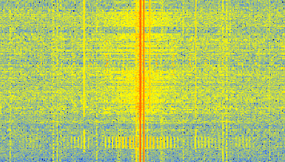
The Meteor-M N2 is a polar orbiting Russian weather satellite that was launched on July 8, 2014. Its main missions are weather forecasting, climate change monitoring, sea water monitoring/forecasting and space weather analysis/prediction.
The satellite is currently active with a Low Resolution Picture Transmission (LRPT) signal which broadcasts live weather satellite images, similar to the APT images produced by the NOAA satellites. LRPT images are however much better as they are transmitted as a digital signal with an image resolution 12 times greater than the aging analog NOAA APT signals. Some example Meteor weather images can be found on this page and the satellite can be tracked in Orbitron or online.
The RTL-SDR and other SDRs like the Funcube along with some free software can be used to receive and decode these images. LRPT images from the Meteor-M N2 are transmitted at around 137.1 MHz, so any satellite antenna like those commonly used with the NOAA weather satellites can be used.
The tutorial also shows an alternative and faster Linux based method using some GNU Radio scripts, but with the final processing still done with Oleg’s decoder in Windows.
The Meteor-M2 SatelliteAn Example LRPT Image Received with an RTL-SDR from the Meteor-2 M2.Another Sample LRPT ImageWhat a LRPT signal looks like in SDR#
For a comprehensive book about the RTL-SDR you may be interested in our eBook available on Amazon.
Some car security systems from around 2001 – 2003 use an embedded RFID tag inside the car key as an added security measure against key copying. Using his HackRF, ChiefTinker was able to analyse and decode the data from an active RFID token used in a car key. He notes that the same analysis could also be performed with an RTL-SDR dongle.
Upon powering the RFID tag with a power supply, ChiefTinker noticed that the tag emitted a short transmission every 5 seconds in the ISM band at 433.920 MHz. On closer inspection he determined that the transmitted data was encoded with a simple AM on-off keying (OOK) scheme. After importing the audio into Audacity and cleaning up the signal a little, he was able to clearly see the OOK square wave showing the transmitted binary data.
Next he analysed the data and compared the binary output against two different RFID keys. From the comparison he was able to determine that the tag simply beacons a unique serial number, which is susceptible to capture and replay attacks. After further processing he was able to convert the transmitted binary serial number into hexadecimal, then ASCII to find the unique serial number being broadcast in decimal.
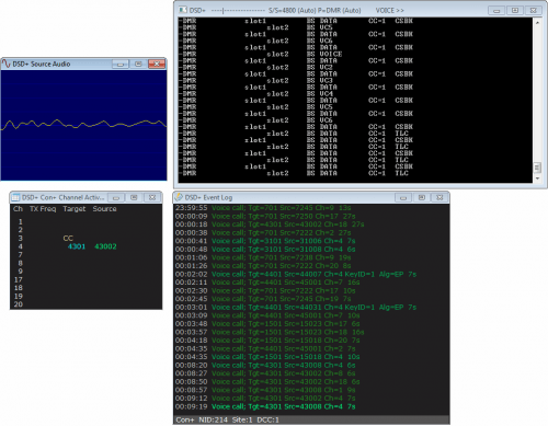
Version 1.5 of Digital Speech Decoder Plus (DSD+) has been released. DSD+ is a popular Windows software tool used for decoding digital speech such as P25 with the RTL-SDR. The latest version comes with a simple GUI interface that has an event log that shows call target and source ID history and an audio waveform plot which can help determine if DSD+ is receiving audio correctly. This version of DSD+ has the ability to decode the following protocols.
D-STAR
NXDN4800
NXDN9600
DMR/MotoTRBO
P25 Phase 1
X2-TDMA
ProVoice
In addition to the above, the new version comes with an LRRP decoder and display program which should allow you to see on a map the GPS location of broadcasting radios.
DSD+ V1.51 can be downloaded from this link. The forum thread on RadioReference where the developer releases and discusses the DSD+ software can be found here.
This version of DSD+ comes with all the files needed to make it run already. To use DSD+ V1.5 simply extract the zip file into a folder and double click on DSDPlus.EXE. DSD+ will listen to your default audio device that is set in the Windows sound recording properties. Simply tune to a digital voice signal in SDR# or any other SDR receiver and set the output audio settings accordingly. To start the LRRP display program simply open LRRP.exe.
TETRA is a trunked radio communications system that stands for “Terrestrial Trunked Radio”. It is used heavily in many parts of the world, except for the USA. Recently, a software program called Tetra Live Monitor (telive) was released on GitHub. This software can be used along with the (patched) Osmo-TETRA software to monitor and listen to unencrypted TETRA communications.
Below we show a tutorial on how to listen to TETRA communications using a RTL-SDR RTL2832U software defined radio. This tutorial is based heavily on the telive_doc.pdf file that is written by the author of telive and included in the telive git download. Please refer to that pdf file for further details on how the software works. We have modified their tutorial slightly to fix some small errors and make it a little easier to understand. As this code is still under heavy development if you have trouble please check their PDF file for modifications to the procedures.
Decoding and Listening to TETRA Tutorial
Most of this tutorial is performed in Linux and we assume that you have some decent Linux experience. We also assume you have some experience with the RTL-SDR dongle and have a decent antenna capable of picking up TETRA signals in your area. If you don’t have a RTL-SDR dongle yet see our Buy RTL-SDR dongles page.
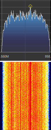
First, we will need to find some TETRA signals. The easiest way to do this is to open SDR# or another program like GQRX and look for them. TETRA signals are continuously broadcasting with a bandwidth of around 25 kHz. There may be several TETRA signals grouped in close proximity to one another. See the example images below.
A Zoomed in TETRA SignalA Grouping of TETRA Signals Zoomed Out
An example audio clip of a TETRA signal recorded in NFM mode is shown below.
Once you have found some TETRA signals, record their frequencies. Now close SDR#, or whatever software you were using and boot into Linux. In this tutorial we use a 32-bit Ubuntu 14.04 virtual machine running on VMWare Player as our Linux system. Some of the commands may vary if you are using a different system.
The TETRA decoding software requires installation of the older GNU Radio 3.6 (latest version is 3.7). The easist way to do this is to run Marcus Leech’s install script with the -o flag, to indicate you want the old version:
This script will run for a few hours and should install GNURadio 3.6 and all the drivers required to run the RTL-SDR on Linux. Note that if you already have GNU Radio 3.7 installed, we recommend installing 3.6 on a fresh Linux install as the two versions many conflict.
Install libosmocore-sq5bpf
cd ~
git clone https://github.com/sq5bpf/libosmocore-sq5bpf
cd libosmocore-sq5bpf
autoreconf -i
./configure
make
sudo make install
sudo ldconfig
Install osmo-tetra-sq5bpf
cd ~
git clone https://github.com/sq5bpf/osmo-tetra-sq5bpf
cd osmo-tetra-sq5bpf
cd src
make
Install telive
git clone https://github.com/sq5bpf/telive
cd telive
make
sudo mkdir /tetra
sudo chown YOURUSER.YOURGROUP /tetra
sh install.sh
Where YOURUSER.YOURGROUP should be replaced with the username and group that you are currently logged in to on your Linux system. In most cases it can just be YOURUSER.YOURUSER. Run ls -l in your home directory to see what username and group your files are using.
Install the TETRA Codecs
Note that if you are running a 64-Bit Linux version you will need to set your system to use a 32-bit compiler. The Appendix of the telive_doc.pdf file shows how to do this.
In the top right enter as a search term “en 300 395-2″ and click the button to select Search Standards.
Start the search.
Find the search result labelled as REN/TETRA-05059.
Click on the winzip icon (looks like a white page with a yellow file cabinet on it) to the right of the result to download en_30039502v010301p0.zip.
Move this zip file into ~/osmo-tetra-sq5bpf/etsi_codec-patches.
In a terminal browse to ~/osmo-tetra-sq5bpf/etsi_codec-patches.
Unzip the file, making sure to unzip with lower case letters by using the following unzip command.
unzip -L en_30039502v010301p0.zip
Use the codec.diff file to patch the codec files you just unzipped by typing the following patch command.
patch -p1 -N -E < codec.diff
Open the c-code folder.
cd c-code
Run make to compile the codecs.
make
Copy the compiled files cdecoder and sdecoder to /tetra/bin by typing the following, or just by copy and pasting them in the Linux GUI.
cp cdecoder sdecoder /tetra/bin
Running the Software
Open a terminal window and browse to ~/osmo-tetra-sq5bpf/src and run ./receiver1 1.
cd ~/osmo-tetra-sq5bpf/src
./receiver1 1
Open a second terminal window or tab and open a specially sized xterm window using the following.
/usr/bin/xterm -font fixed -bg black -fg white -geometry 203x60
In the xterm window, browse to ~/telive and run ./rxx.
cd ~/telive
./rxx
Open another terminal window or tab and browse to /tetra/bin and run ./tetrad.
cd /tetra/bin
./tetrad
Open another terminal window or tab and open GNU Radio Companion by typing the following.
gnuradio-companion
In GNU Radio open the telive_1ch.grc file which is found in ~/telive/gnuradio-companion.
On the left of the GNU Radio flowgraph, double click on the variable labeled Center Freq and change the frequency to the frequency of your TETRA signal that you found earlier subtracted by 500 kHz. E.G. If your TETRA signal was found at 858.562 MHz, you’d type your center frequency as 858.062 MHz. This is because the default offset value is set to 500 kHz.
Double click the variable labelled ppm and input your dongles particular PPM correction value.
Execute the flowgraph by clicking on the cog icon on GNU Radio Companion toolbar.
At this point you should confirm that you see a strong rectangular TETRA signal in the FFT window that pops up. If you do, switch back to your first terminal window where you ran ./receiver1 1. You should confirm that you see system data scrolling by. If there is no data scrolling by, try adjust the gain and PPM offset in the FFT window.
If data is scrolling and the system is not encrypted you should start to hear voice audio. If a system is capable of encryption, the terminal window with the system data will show Air encryption: 1. However, note that even if it shows this, there is still a possibility that encryption has not been enabled.
If you want to log all voice communications you can by pressing “shift+R” in the telive window. This will log .ogg audio files to /tetra/out. You can also enable a text log with “l”.
If you happen to close the GNU Radio FFT window and want to run the program again, you will need to restart the ./receiver1 1 program.
To see how to monitor two or four TETRA channels simultaneously, refer to the telive_doc.pdf PDF file.
TETRA Decoding Windows
If you enjoyed this tutorial you may like our ebook available on Amazon.
Over a year ago we wrote a tutorial on how to analyze GSM cellular phone signals using a RTL-SDR, a Linux computer with GNU Radio, Wireshark and a GSM decoder called Airprobe. With this combination it is possible to easily decode GSM system messages. Setting up Airprobe is can be difficult as it is unmaintained and incompatible with the new version of GNU Radio without patches.
Now a new software package called gr-gsm has been released on GitHub which seems to be a newer and improved version of Airprobe. The gr-gsm software is also much easier to install, uses the newer GNU Radio 3.7 and seems to decode the system data with much less trouble than Airprobe did. We will soon update our tutorial to use gr-gsm, but the instructions on the GitHub are already quite good. The author of gr-gsm also appears to be actively adding new features to the software as well. The video below shows gr-gsm in action.
Over on YouTube user Jane feverlay has uploaded a video showing a new AIS decoder called AISRec for Windows that he has developed.
AIS is an acronym for Automatic Identification System and is a system used by ships to broadcast position and vessel information. By monitoring AIS transmissions with the RTL-SDR we can build a boat radar system. We have a tutorial on this here.
The new software is not free, but he offers a trial version that limits the run time to 20 minutes and 5000 max messages. The paid version removes these limits and also decodes both AIS channels simultaneously. The program monitors data from the RTL-SDR and sends decoded data out via UDP. Software such as OpenCPN can then be used to display the AIS data on a map.
We tested the trial version on our machine and found that it worked well at decoding AIS messages. To download the trial go to http://pan.baidu.com/s/1pJiEzEV and enter the code kn44. The download site is in Chinese, but it is obvious where to enter the code. We found the software to be virus free, but remember to always scan unknown software like this yourself. The full price of the software is unknown, but purchasing instructions are given in the trial download readme. The author also writes that his software now supports the Airspy, but not in the trial version.
Note that we discovered that the software doesn’t use a PPM correction setting as expected. Instead it uses a frequency shift setting. To set the shift in the AISRec.ini file, we had to calculate freqshift = 162.025 MHz – frequency of the second AIS channel as shown in SDR# with no PPM correction set.
To gather the power usage data he used an RTL-SDR connected to a PC running rtlamr, which is software that can read data from ERT compatible power meters that transmit in the 900 MHz ISM band. He also uses some custom code he wrote that automatically plots the data over time and allows him to integrate it with his home automation system. In addition to his post he also uploaded a video shown below that shows his system in action.
Over on YouTube user BSoD Badgers has uploaded a video showing his reception of FreeDV digital speech at 14 MHz. He uses SDR# combined with the FreeDV software to decode the signal.
FreeDV is a open source software application that allows digital speech to be sent at HF frequencies in a 1.25 kHz wide signal. The same software can be used on the receiving end to decode the signal into speech.
Recently RTL-SDR.com reader DE8MSH wrote in to let us know about his experiments with receiving WSPR with his RTL-SDR. WSPR is an acronym for “weak signal propagation reporter” and is a software program and RF protocol designed for very weak signal radio communications between ham radio users. With less than 5W of transmitting power, a WSPR signal could potentially be copied all over the world.
To receive WSPR, DE8MSH used a direct sampling modified RTL-SDR dongle together with a 9:1 unun, 10m RG58 coax cable from RTL-SDR to unun and a 12m wire antenna outside his house. Then by using SDR# together with the WSPR software he is able to copy signals from all over Europe and Canada/USA from his home in Germany.
Some Received WSPR LocationsWSPR Report InformationThe WSPR Software
Earlier this year the American TV show Good Morning America featured a segment on software defined radios being used to break into houses with wireless alarm sensors. The story is based on a Defcon 2014 paper “Home Insecurity: No Alarms, False Alarms, and SIGINT” by Logan Lamb. In the TV segment Logan shows how he uses a USRP software defined radio to send a false alarm signal, jam a wireless sensor and finally to record sensor activation data from the alarm system.
Although Logan used a USRP, the same attack could be done with the cheaper HackRF.
Over on YouTube user Samy Kamkar has uploaded a video showing how he was able to use an RTL-SDR to copy his friends wireless doorbell signal and prank him by replaying it using an Arduino and 433 MHz transmitter. His video goes through the entire reverse engineering process he used from recording the wireless doorbell signal with the RTL-SDR, to analyzing and understanding the signal and finally to programming the Arduino with the code to replicate the doorbell signal.
A few days ago the Chaos Communications Congress (a technology and hacking focused conference) commenced. Amongst the talks there was one about reverse engineering the Iridium satellite paging system using software defined radio. Iridium satellites provide global communications via special satellite phones, pagers and other transceivers.
In the talk the speaker shows how they used a USRP radio together with a cheap active iridium antenna, a bandpass filter and an LNA to receive the Iridium satellite signals. They also mention that an E4000 RTL-SDR together with an LNA and appropriate home made antenna for frequencies in the ~1.6 GHz region can also be sufficient.
Once they were able to receive signals they were then able to reverse engineer the signal and create several pieces of software to decode the pager messages. The code is available on their GitHub at https://github.com/muccc/iridium-toolkit.
Over on YouTube user Tom Mladenov has recently been using his RTL-SDR to listen to EPIRB distress beacons transmitted by the SARSAT payload carried by the NOAA 18 satellite. To do this he uses a 6.5 turn helix antenna that is resonant on 1.5 GHz.
An EPIRB is a maritime device that is used to send out a distress beacon for vessels in serious trouble. The EPIRB beacon transmits data that contains GPS coordinates of the vessel at 403 MHz to the satellite. The data is then retransmitted to a mission control centre at 1.5 GHz.
Note that the professional version of MultiPSK can be used to decode EPIRB signals.